Showing posts with label Project. Show all posts

Tuesday, June 4, 2013

ARDUINO TFT TOUCH 3.2in LCD DISPLAY


IMG_20130604_142024

I hooked up a 3.2in TFT Touch LCD Display to my Adriano. The applications for this are endless. Digital picture frame, a secondary monitor for my PC to display the status of my PC, and tiny touch screen applications. Is it worth investing the time to write all the necessary libraries and build these applications though? Probably not, writing the same applications for an Android Smartphone would be more productive.

A simple library for this display is already available. I’ll look into writing a simple app the next time I find myself with too much time.

Saturday, June 1, 2013

Ruger 10/22 Ultimate

2012-10-24 20.12.23

The Ruger 10/22 is one of the most popular semi-automatic rifles out there. They’re reliable, affordable, versatile, accurate, and easily maintained. With such a large following behind them, all kinds of after market parts are available. A complete custom precision rifle can be built to your specifications with only aftermarket parts.

This post documents the changes made to a Ruger 10/22 Carbine to convert it into a target rifle. With the exception of the trigger group, all the upgrades made to the rifle are relatively simple drop-in replacements. The most difficult part of this conversion would have been obtaining the different components needed to complete this project because availability of aftermarket parts isn’t the best here.

A shout-out to the members of Canadian Gun Nutz and Rimfire Central for knowledge they shared to make this project a possibility.

Disassembling the 10/22

The Ruger 10/22 Carbine

IMG_0386

Here’s the Ruger 10/22 Carbine that will serve as the base for this project. No modifications have been made to the rifle, except for the addition of a 3-9mm Bushnell scope.

Removing the Stock

IMG_0387

Removing the barrel band.

IMG_0390

Removing the takedown screw.

IMG_0391

The safety catch needs to be halfway between safe and unsafe positions in order for the action to be removed from the stock.

IMG_0392

The stock now simply slides off the action of the rifle, allowing me to change the internals of the rifle.

Disassembling the 10/22

Trigger Work

The trigger group is the mechanism that initiates the firing sequence. The pull (or resistance) of the stock trigger is set to 6-8lbs.  A lighter trigger pull is ideal on a target rifle because it minimizes the amount the rifle is pulled off target when the trigger is squeezed. For this project, the professionals at Brimstone bought the trigger pull down to 2.5lbs.

IMG_0393

The trigger group easily separates from the receiver by removing the pins indicated in the figure above. Simply push them out. I used hex screws. Do remember to set the bolt in the closed position first.

IMG_0430IMG_0434

Here’s a side and top view of the trigger group before it was sent it off to the gunsmiths for modifications.
IMG_0908IMG_0907

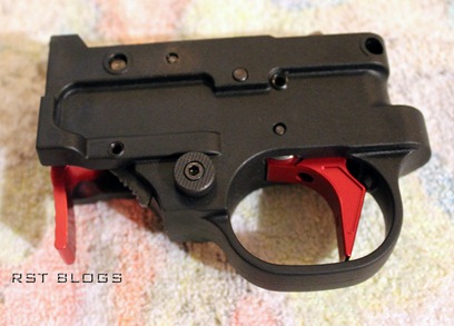
Here’s the trigger group after a three month long wait. Notice the internals in in the top-down view has been cleaned and polished? Below is a list of all the work done.

  • The trigger pull has been brought down to 2.5lbs.
  • There is no noticeable movement when pulling the trigger, just crisp and sudden click.
  • An auto-bolt release modification has been done; the bolt now closes without having to fumble with the bolt lock. Only pulling the bolt further back is necessary.
  • The disconnector, and hammer has been polished for to reduce friction of the internal mechanisms for smoother performance.
  • The hammer has been reshaped.
  • A wider red trigger has been fitted and installed into the trigger group.
  • The trigger return spring has been replaced with a torsion type spring and an over travel stop.
  • The magazine push release has been replaced with a larger red pull release to match the red trigger.
  • The sear is replaced with a adjustable sear.
  • An over-sized safety is installed.

In short, the components of the trigger group have either been replaced or polished in an effort to change the feel of the trigger and make the rifle marginally more accurate.

The Receiver and Bolt Assembly

IMG_0900

The internals of the receiver can now be accessed with the trigger group removed, but the barrel was removed too so the receiver would be more manageable. It will be replaced later anyways.
IMG_0901

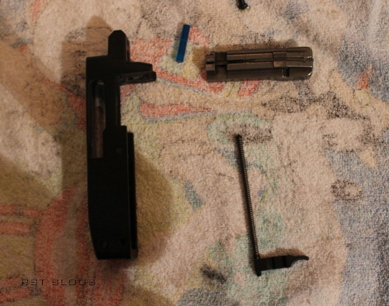
Here’s the bolt assembly, bolt buffer, and charging handle separated from the receiver. The stock steel bolt buffer is replaced with a Tuffer Buffer polymer buffer. This will eliminated metal on metal contact when the bolt is pulled back, removing that metal clang when the bolt is pulled back. Moreover, it should dampen vibrations within the receiver during semi-automatic operation and theoretically improve accuracy (marginally).

No modifications have been made to the bolt, however, it can be polished to reduce friction for smoother operation which could improve accuracy (again, marginally). A polished bolt is mainly more for aesthetics.

The casing extractor in side the bolt has been replaced with a Volquartsen Edge Extractor (on the right in the figure below).

IMG_0767

This is an upgrade made not to (marginally) improve accuracy, but rather, improve functionality of the rifle with my aftermarket components. This new claw has a a sharper edge, allowing it to better clasp the casing of a spend .22LR round and extract it from the action of the rifle. This new extractor is necessary as the new barrel I am using (further detailed in the the subsequent subsection) has tighter tolerances; the round just fits through the barrel so the casing may difficult to remove.

Upgrading the stock aluminum alloy receiver to an aircraft-grade aluminum receiver was considered. However, such an upgrade would offer only a few benefits. The rifle with the upgrade would be (marginally) lighter, however, this target rifle will be shot from a bench or from the prone position where a bipod will endure most of the weight of the rifle. With the a new receiver costing as much as a complete new rifle, the upgrade will be held off (for now).

With the bolt removed from the receiver, now is also a good time to replace the charging handle.

IMG_1178

A red charging handle to match the trigger and magazine pull release is used. Performance wise, the weight of this new charging handle is different, it will (negligibly) affect the bolt during semi-automatic operation.

Barrel

A new barrel would be the single best one can make to the Ruger 10/22 upgrade to improve accuracy.

IMG_0898

A 20 inch .920 Green Mountain Fluted Bull was chosen. Keep in mind, when installing a new barrel, the notch on the barrel should be aligned with the extractor on the bolt.

IMG_0902

Barrel installed. It will be left free-floating against the new Hogue stock (detailed in the next section). Hopefully, barrel droop will not be an issue.

IMG_0910

Putting it back together

Barrel

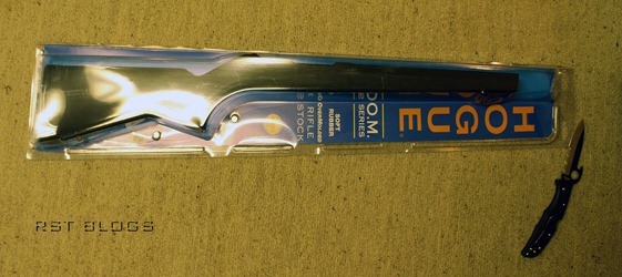
Everything will be put back together in a Hogue Overmold Stock.
IMG_0766

The Hogue stocks have the benefit of being coated in rubber, making them more comfortable to hold than the factory stock. They also have swivel studs installed allowing for the installation of a bipod or sling.

IMG_0912

I also replaced the stock takedown screw with this new Volquartsen takedown screw which utilized a hex key instead of a flat head screwdriver. Why? I lost the stock screw. The benefits of this new takedown screw is that it can be tighten tighter by hand easier with a hex wrench.

Rifle Scope
IMG_0917

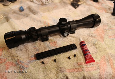
Seen here is a Bushnell 3-9mm rimfire rifle scope, weaver rings, the factory rail (which will later be replaced with an red anodized rail) and some Blue Loctite to hold everything together. This low budget scope offers very bright magnification.

IMG_0918

Rail installed. The charging handle wasn’t replaced in this picture.

Bipod

IMG_0896IMG_0916

The purpose of the bipod is to act as a forward rest for the rifle and reduce motion when aiming the rifle. Installing the bipod was pretty straightforward. Simply the adapter onto the forward swivel stud on the stock, and then the rail onto the adapter. Next, install the bipod onto the rail.

THE FINSIHED Product

Rifle Scope

IMG_0915

Function tests were performed with dummy rounds, just to ensure everything works. The hammer strikes the rounds when the trigger is pulled, and the bolt extracts the dummy rounds (most of the time). Everything appears to be good.

IMG_1182

IMG_1183IMG_1187

IMG_1184

The next steps are to take it out to the range, sight in the scope, and fire off a few rounds.

Monday, April 1, 2013

Arduino 16*2 LCD, Ultrasonic Sensor, and Temperatur Sensor

OBJECTIVE

It has been a while since I've done some work hobby work with the Arduino prototyping microcontroller. I decided its time to dig out my kit and build something and reacquaint myself. Something simple to start, yet new.

Main Components

  • Arduino Uno 
  • HD44780 16*2 LCD display
  • SR04 Ultrasonic Range Sensor
  • LM335 Temperature Sensor

Design


Working with an LCD display can make things simpler. Generally, I used the LCD display to display sensor information but it can also be used to display the stages of the code written running. This comes in handy for debugging and gives me the option of not having to rely on the serial monitor.

Unfortunately, the LCD display takes up a lot of pins on the Arduino board, just look at tutorial here.
The solution; I bought an IIC serial mondule to act as the interface between the Arduino and LCD display. The LCD display now only requires two pins, the serial port on the the Arduino, A3 and A4.

Well now that I have the LCD display working after some trouble finding the correct libraries, I need to find some information to output on it. This is where  the ultrasonic range sensor comes in. They're pretty easy to work and generally pretty accurate. A line of code to to make the calculation for distance given time it takes for the ultrasonic wave to bounce from the emitter to receiver and speed is all that's needed.

distance = (duration/2) / 29.1;

As you can see, that's pretty close. My tests indicate the accuracy starts to decrease when distance sense reaches above 1m despite the manufacturer says its good for up to 4.5m. Maybe I need to fine-tune my code a bit or there's some interference.

Now that I have the distance sensor working and the LCD, there a number applications I can think of just by adding more lines of code and maybe a button or two for user input.
  • Door Alarm/Greeter
  • Motion Detector
  • Height Finder (through the use of triangulation)
Now I have one more component to add, the temperature sensor. The voltage output of the sensor scales linearly with ambient temperature, so calibration would be pretty simple. For this quick project, I didn't bother. Since I wanted a portable device, I added a power supply module for my breadboard as well.

A few more lines of code and some time wasted troubleshooting the code only to discover the problem was a lose wire, here's the result:

I'm have not come up with any ideas for applications for a device needs both the temperature and distance, but it's great to see everything working as intended. If I push my creativity further and spent a few hours writing some code, I'm sure I can find a few interesting applications for these two sensors. I should probably calibrate the temperature sensor though, 70 degrees is way off.


Wednesday, January 23, 2013

The Escalade: Autonomous Search and Rescue Robot Part 1

Objective

The goal is to create an autonomous search and rescue robot, capable of applying a mapping, and search and rescue algorithm and retrieve a target on a model scale. Collected data will be wirelessly transmitted to a control computer via an XBee Module.
A printed maze is used to simulate the bounded navigable terrain and a golf-ball serves as the target for rescue.

The Team 

  1. RST - The team leader, responsible for managing project deadlines, submissions, and scheduling. RST also contributed to the overall hardware design of robot and was responsible for building the internals and assembling the robot. Under RST's unparalleled leadership, the team mustered more man-hours from its members and completed more revisions and prototypes of the robot than any of the team's competitors. The result, despite a few major setbacks, the team built superior robot compared to its competition, the Escalade.
  2. KGL - The team's lead software developer. KGL was responsible for nearly all the software aspects of this project from creating the foundation of the robot's search & rescue algorithm to integrating the software to function with a wireless Xbee module. Moreover, KGL single handedly create the GUI on for the remote control.
  3. WCC - The team's second hardware designer, hardware integration officer expert, and secretary. WCC designed and aided in the building of the robot's motor control module. WCC also took on the task of integrating the hardware together and patiently tested nearly every hardware component to discover and eliminate hardware problems. Lastly, WCC was responsible for keeping track of the accounts and did a fine job; the numbers balanced out at the end.
  4. BPY - BPY was responsible for CAD drawing of the robot's chassis and then building the chassis. It was crucial all the hardware components fitted together so BPY created revision after revision to ensure all the tolerances were met and contributed in the construction of all the prototypes and subsequently the final version of our robot, the Escalade. Lastly, BPY, aided KGL in the development of the robot's software and created one of search and rescue algorithms.
  5. ABC - ABC's official title is the integration and testing officer. Despite ABC's great effort, the responsibilities assigned were too much for ABC. ABC subsequently functioned as a live soldering vise and was assigned one of the most important responsibilities, getting the coffee. Unfortunately, even that was somehow too difficult.

Design

Micro-controller & RF Communications

For our micro-controller, we went with an Arduino Mega 2560 instead of the cheaper Uno. Planning ahead, we expect the additional digital pins may come in useful later on. If not, there's always the option of expansion.
For wireless communications between the robot and PC, we used a XBee module and a Xbee USB dongle.

Algorithm

We know two things about the maze our rover has to navigate. The starting point will always be at the bottom left while the exit will be located at the top right. 
To map and solve the maze, we applied the right/left-hand-rule for solving mazes. The coordinates of the intersection tiles will be recorded relative to the starting point and displayed on the GUI (below). The shortest path solution will then be determined with the fully mapped maze and then traversed by our robot.

Motors

The critical component for moving the robot, we used a pair 29:1 gearbox motor with an integrate encoder (found here) to keep track of the revolutions of the motor shaft. Knowing the number of revolutions will give us a more accurate estimation of distance travelled based on the diameter of the wheels and allow for greater control.
At 12 volts, the motors an run at up to 350RPM, allowing for greater speed. However, this includes a drawback of a high stall current require us to design and build our own motor control module described in the next subsection.

Motor Module

The motors themselves are useless without a method of applying logic to them to control the direction and speed of rotation. This is where the motor module comes in. While module modules can be purchased ready to use, we were unable to find one that would fit the specifications of our motor with a stall current of 5A. Pre-assembled motor control modules are mostly only available at about 2A. As a result, we designed and built our own motor control module.
WCC designed the following schematic for our motor control module. Two of these were put together, one for each motor.
This motor control module serves as the interface between the micro-controller and motors.  Two digital pins are inputted into the control module to the rate of rotation, one for each direction.

Infrared Sensors


In order to solve the maze, we needed sensors to detect the paths and boundaries of the maze. For this task, we used pairs of IR emitters and sensors. Knowing the paths and boundaries are marked in black, the sensors will detect a different reading from the IR emitters emitting against a black object as opposed to a white object. Six pairs of sensors & emitters were placed strategically around the based of our robot to follow the maze.


Chassis


We wanted to build something easy to assemble and large enough to house our internal components, so we opt for something in the shape of the cube. The chassis has went through more revisions than another of our major components. BPY created the CAD drawings and had the aluminum pieces cut out with a water jet. Subsequently, the pieces were folded to shape and powder-coated red.


Rescue Mechanism

We implement the rescue mechanism with a door and servo motor at the front of the robot. As the robot approaches the target, the door opens up and closes over the target, capturing or rescuing it.


Circuitry

Using the free version Eagle PCB design software, we were able to connect all components together on a 8cm by 10cm PCB. Due to the dimensional restrictions of the free version of the program, we really had to cram all the components together tightly. Despite the tight dimensions, we were still able to incorporate the team's logo and names onto the board. Over coming the size restrictions would have allowed us to add male pins to the board so the Arduino microntroller can be plugged directly to the board, effectively, creating a custom shield for the Arduino. The schematics were first draw out and then converted to a CAD PCB drawing which was subsequently sent to be commercially etched out.


End of Part 1